Smart Lock With Face Recognition – How to make –
Various articles explain this topic.
Smart Lock With Face Recognition – The Function and Setup –
Smart Lock With Face Recognition – How to make –
Smart Lock With Face Recognition – Verification –
Making of smart locks – Hardware –
Concept of lock and release
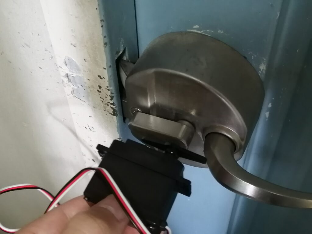
In this article, thumb turn locks are targeted to make. In many mansions or apartments, this thumb turn locks are used. In this time, the motor gets fixed and make thumb turn locks rotated by the motor torque.

Concept 
finished
Necessary parts to get thumb turn locks released with a servo motor
To realize the concept, you need to make below parts with 3D printers.
- A part to transmit motor’s torque to locks
- A part to fix not to rotated the motor by itself
Let’s understand thumb turn locks characteristic to make these parts.
Understanding characteristics of locks or motors
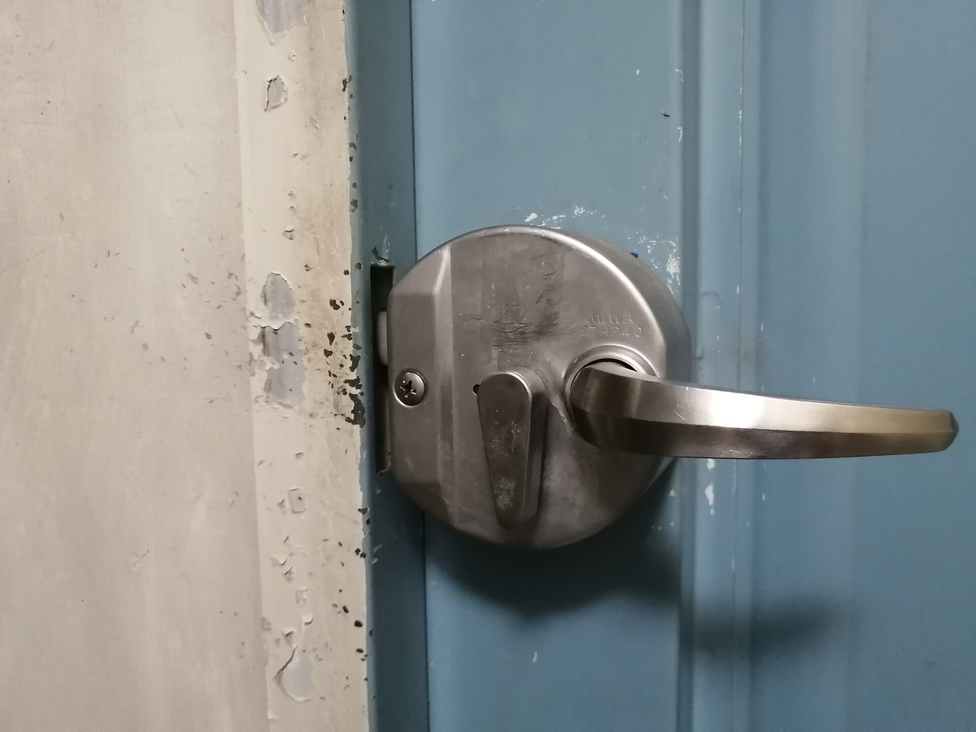
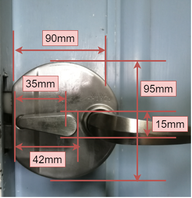
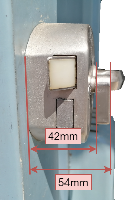
As an example of my home’s locks, I explain how to understand characteristic of locks to make smart locks. Below pictures are locks of my home and it is consist of thumb turn to make a dead bolt in and out and a cylinder.

Open 
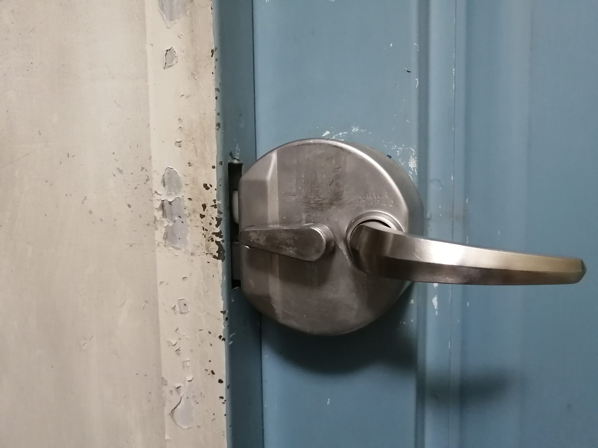
Close
Relationship between state of lock or release and operation of servo motors
- In open, thumb turn is downward
- In close, thumb turn is leftward
So, motors operation get below.
- Close → Open : make a thumb turn 90 degrees of clockwise rotation by servomotors torque
- Open → Close : make a thumb turn 90 degrees of anti-clockwise rotation by servomotors torque
Making parts with 3D printer
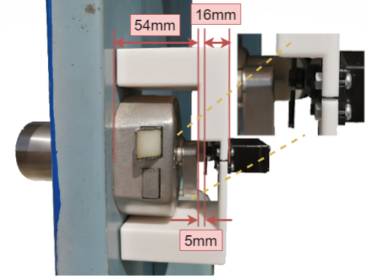
Based on actual size of thumb turn and servomotors, You make 3DCAD data, STL file, with Autodesk Fusion360. It is good to make virtual size of parts bigger than actual size.
Actual size of thumb turn keys
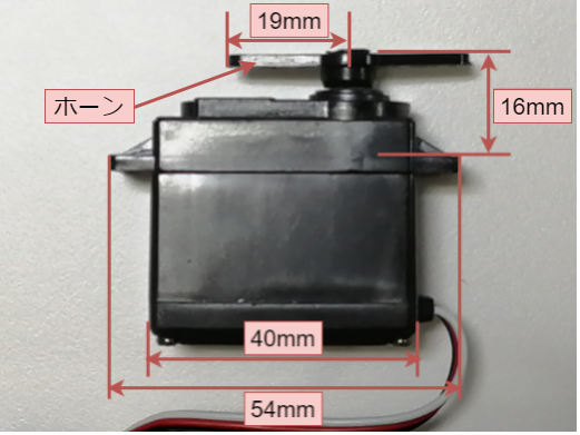
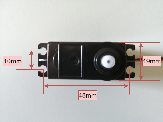
Actual size of servomotors
Parts to transmit torque of servo motors to thumb turn
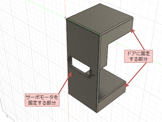
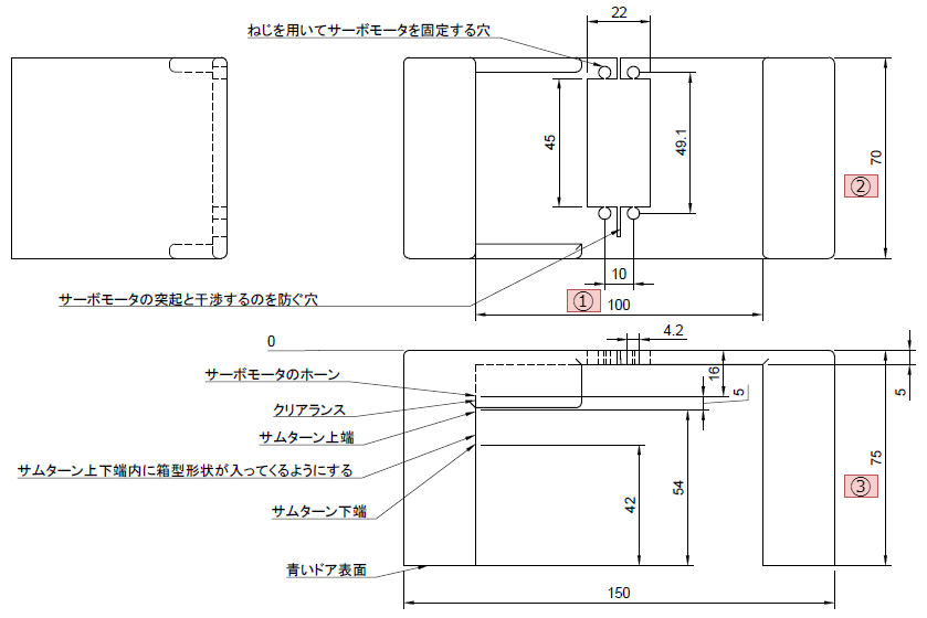
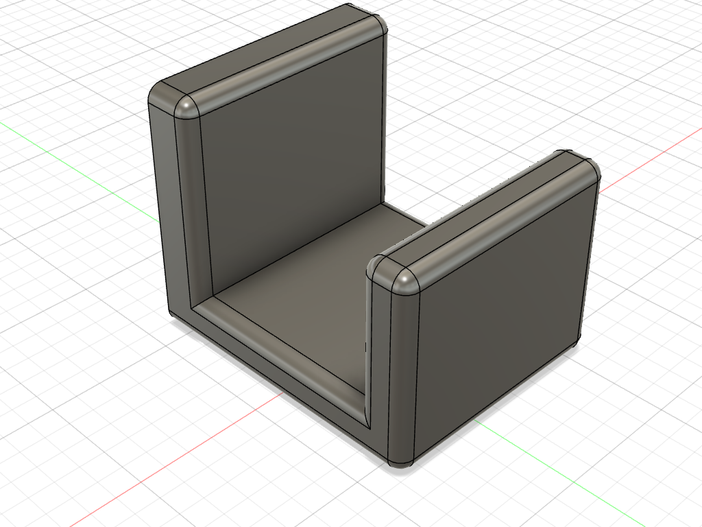
Below images are examples of 3DCAD.
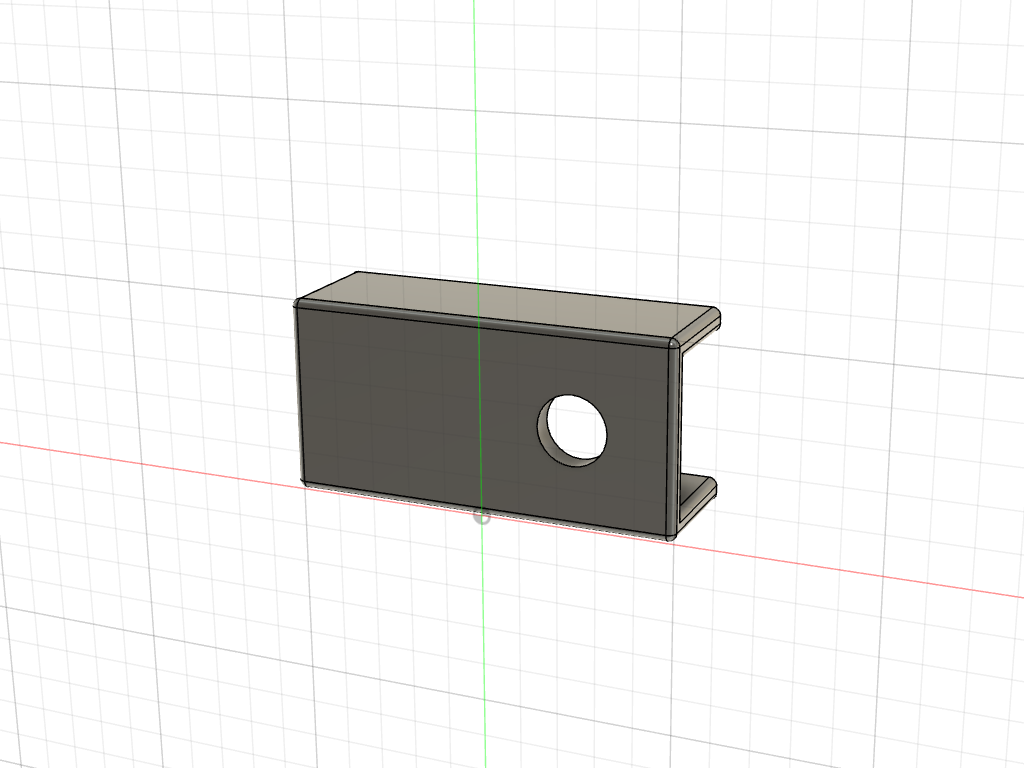
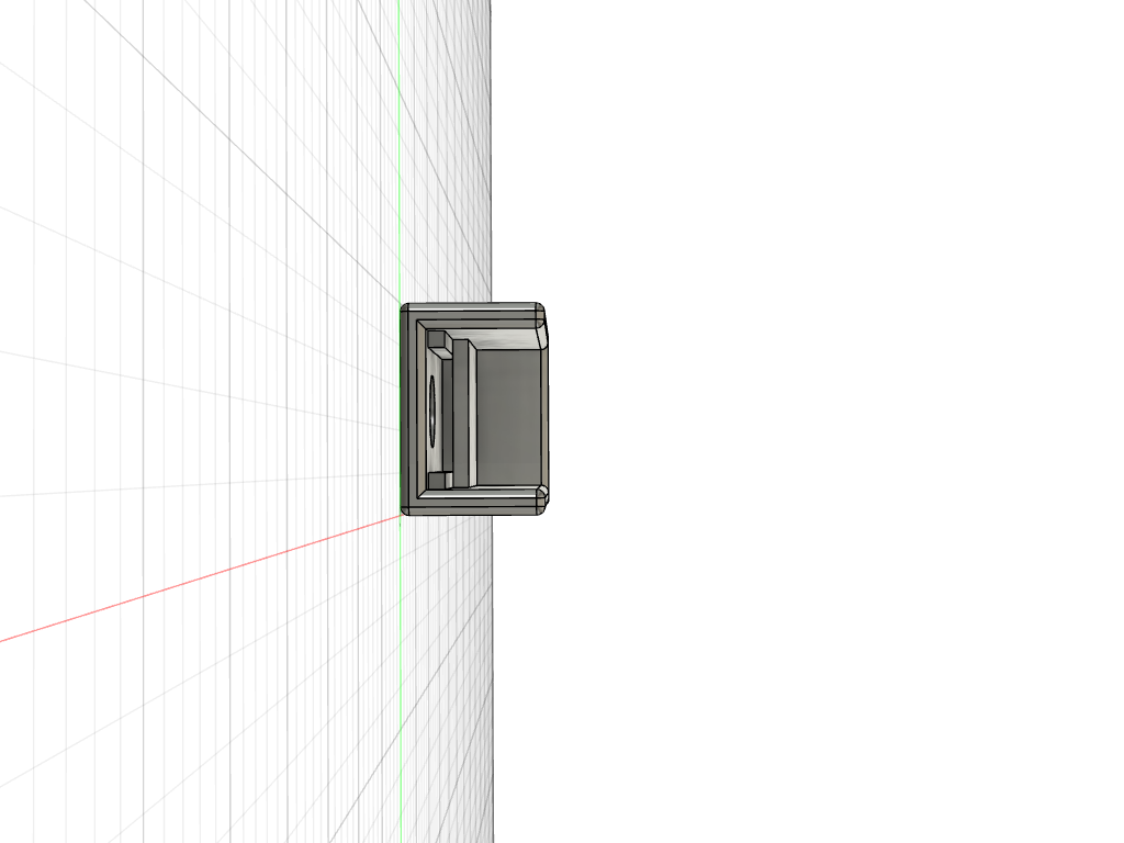
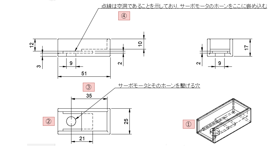
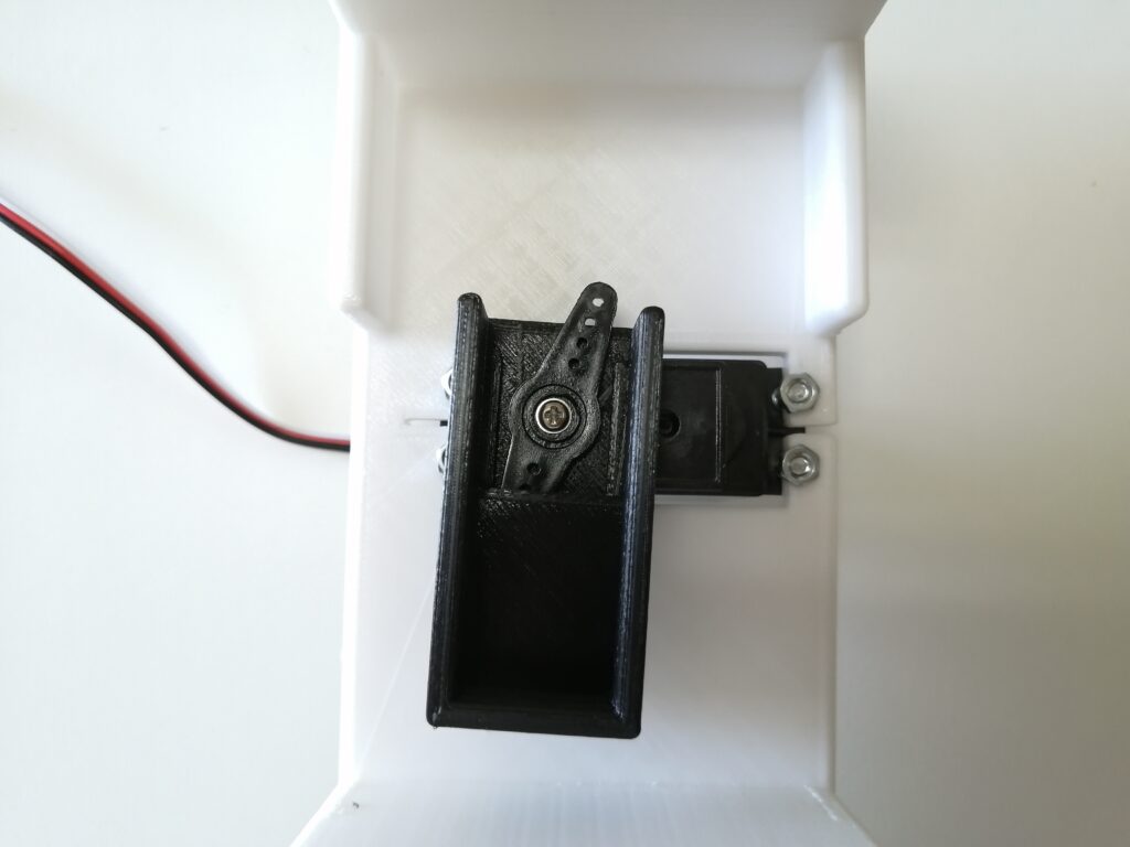
- To transmit torque to thumb turn, you make a box to cover thumb turn(①).
- You make a hole connecting a motor and horn(②). You regulate box size as the center of hole and axis of rotation of motors. (③)
- A box has a fixer to prevent servo motor’s axis from wobbling. (④). The fixer has a gap and the horn fits in the gap.
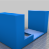
STL files are below.
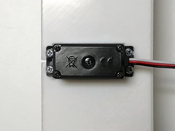
Fixer of servo motors
3DCAD data of fixer of servo motors are below.
Fixer of servo motors are compose of fixer of servo motors and secured parts to the door.
STL files are below.
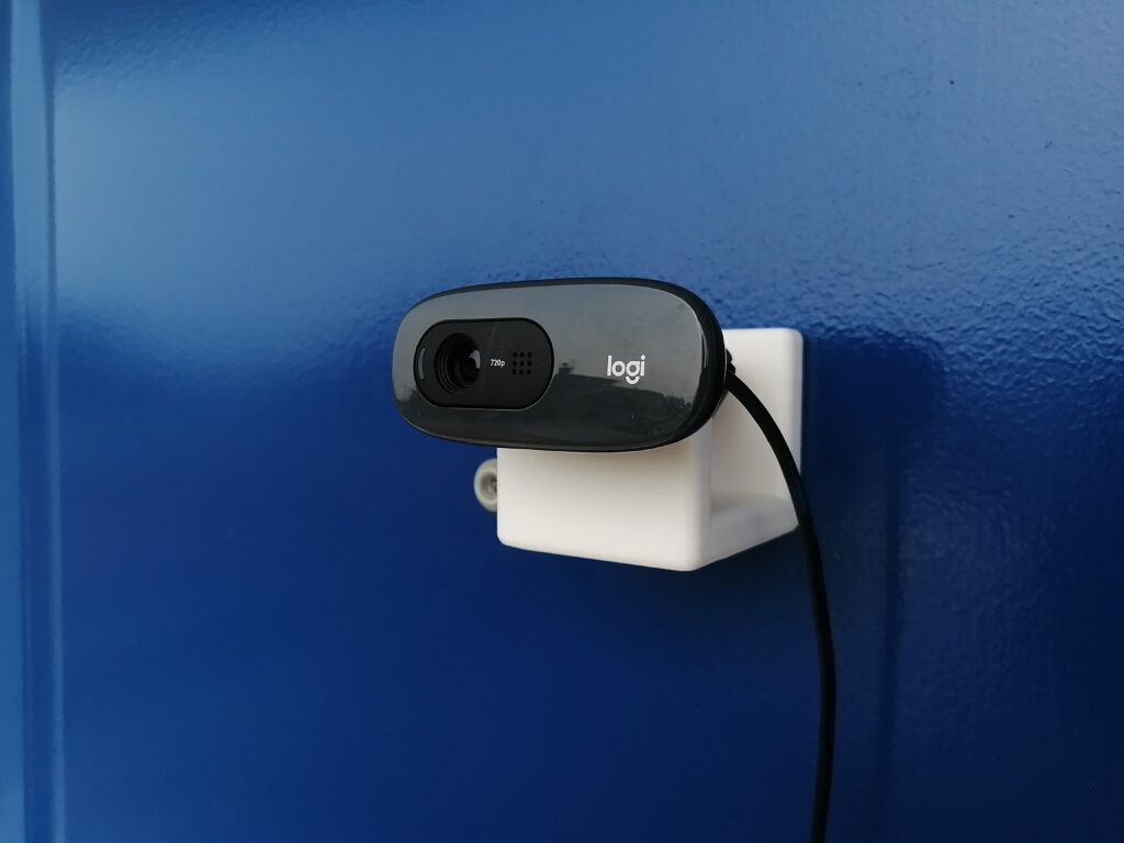
Fixer of USB Camera
USB camera’s 3DCAD data is below.
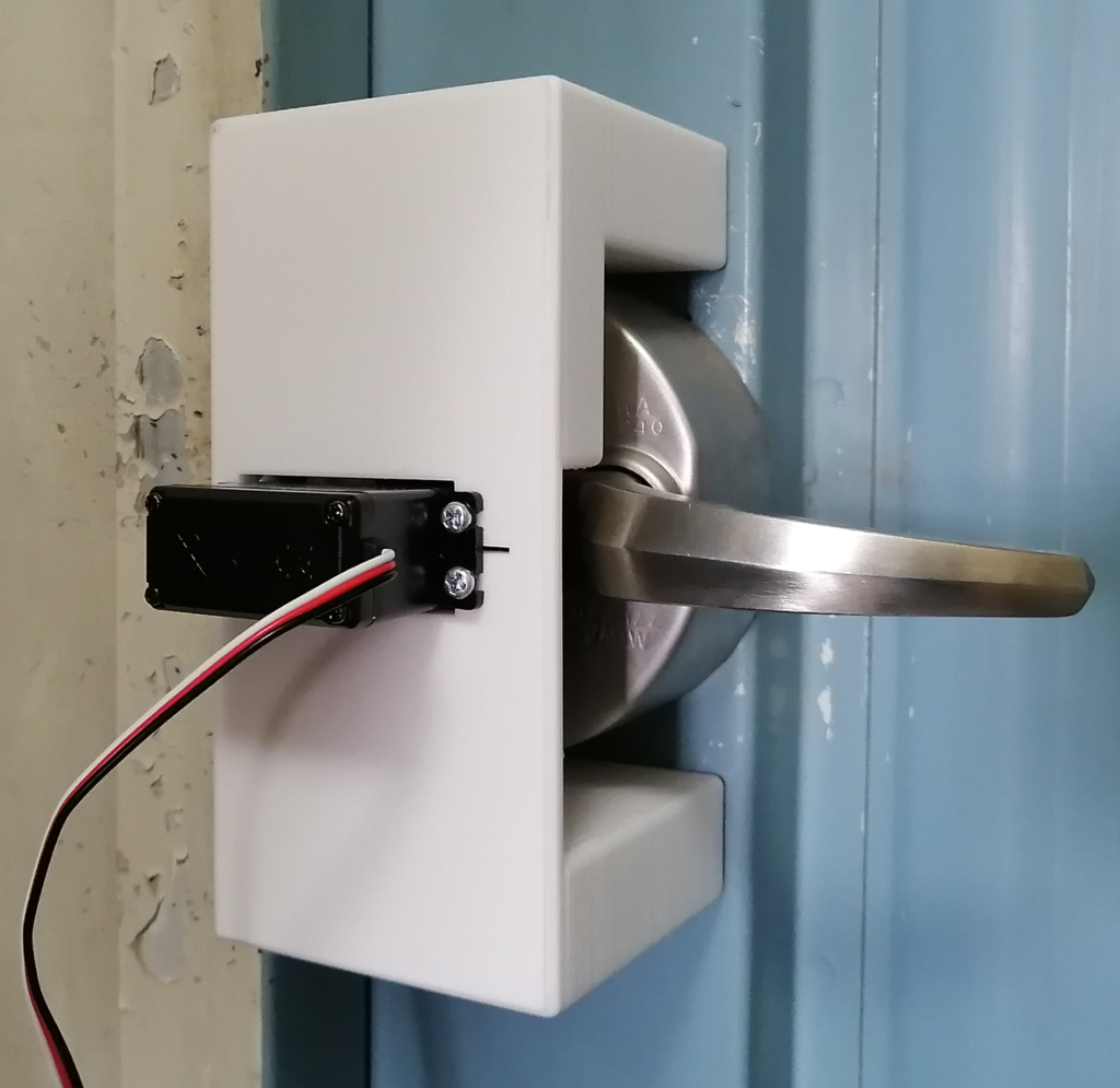
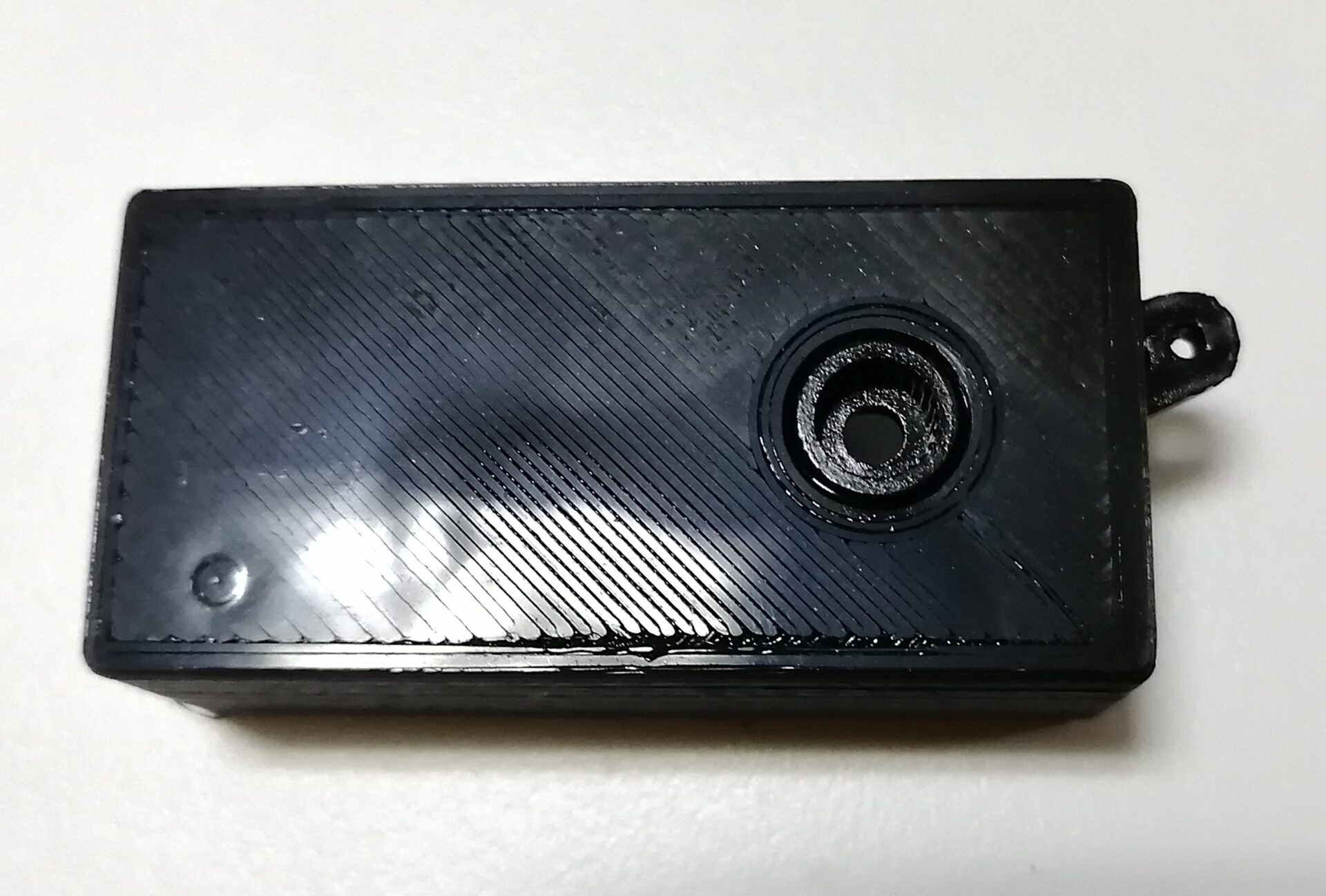
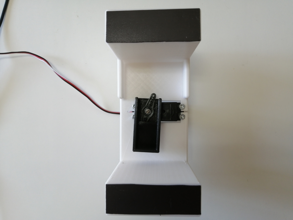
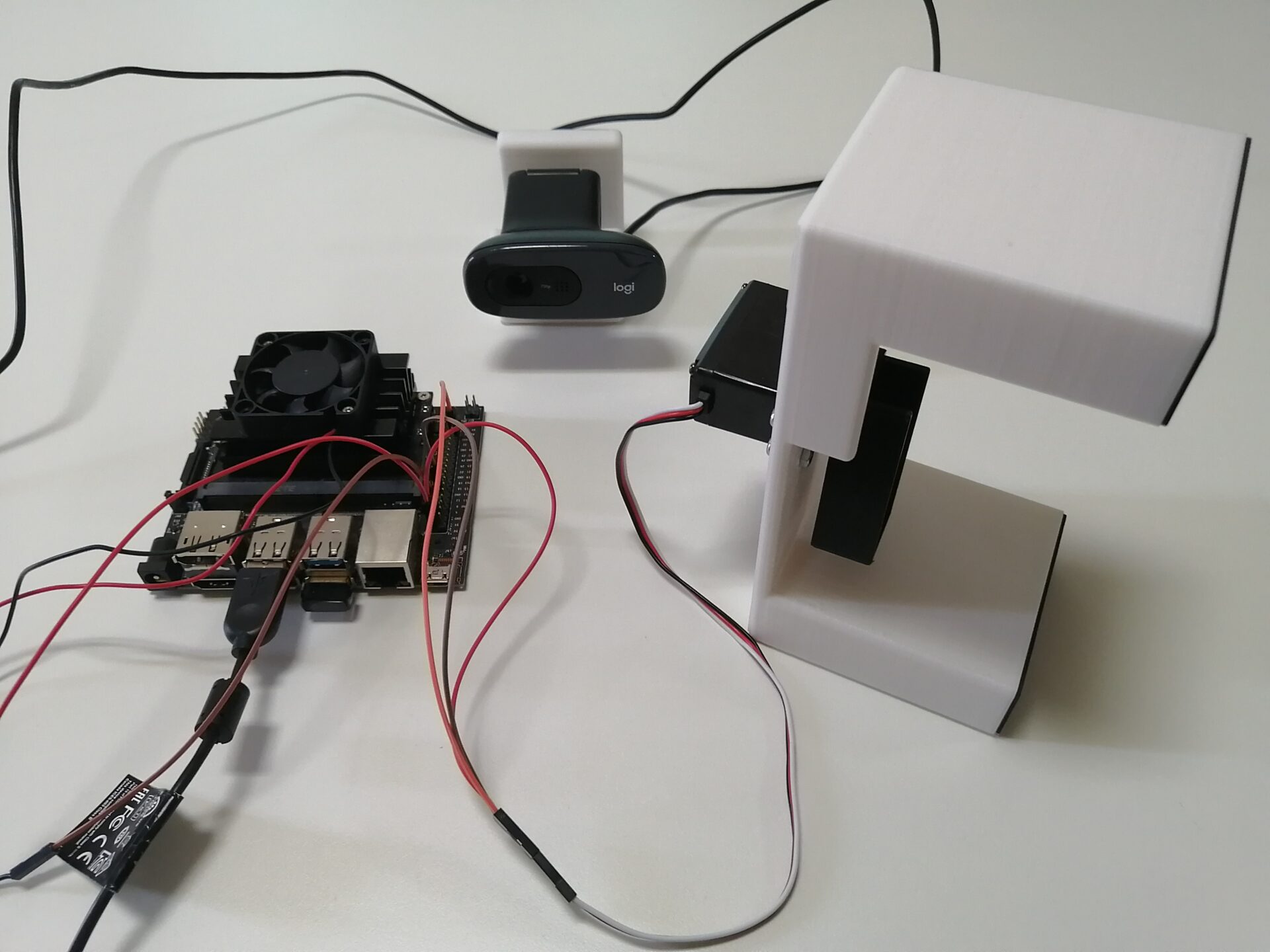
Assembly
After making parts with 3D printer, assemble them.
- A horn fits in gap of a box
- Fix motors to a box with M3 screws
Making of smart locks – Software –
Getting sources
Let’s launch Jetson nano, move to home directory with command prompt and get sources for Smart Lock.
git clone https://github.com/tech-life-hacking/SmartLock.git

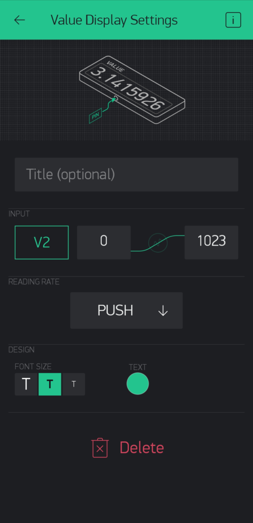
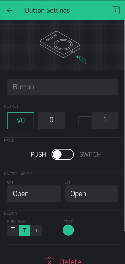
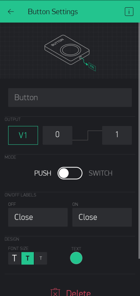
Setup Blynk
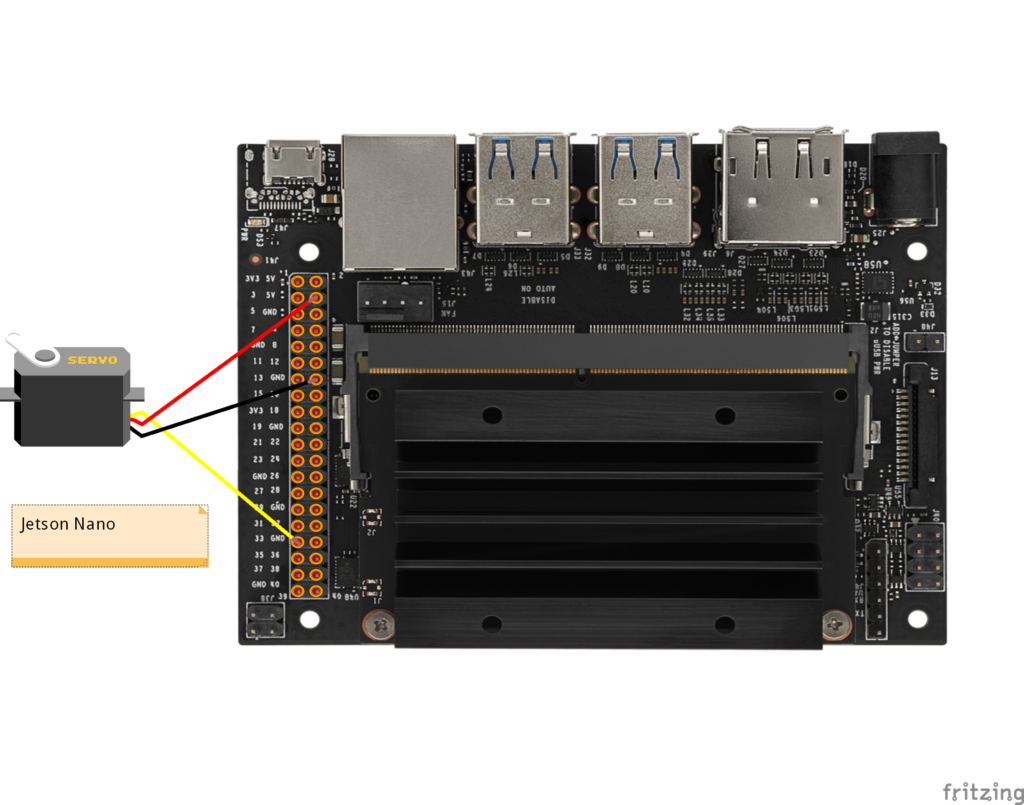
In addition to information of face recognition, motors are driven by Blynk, so setup it.

Adjustment of servo motors
Let’s adjust motor torque. At first, open SmartLock.py.
cd SmartLock
#open SmartLock.py with gedit
gedit SmartLock.py
Let’s edit duty cycle values driving motors.
#change YOUR_AUTH to code that get in a e-mail from Blynk
BLYNK_AUTH = 'YOUR_AUTH'

#edit values to be able to drive thumb turn
opendutycycle = 11.15 #open operation value
closedutycycle = 7.00 #close operation value

#check operation
sudo python3 SmartLock.py
Preparation of images for Face recognition
Let’s prepare your five images in picture_of_me folder. Compared with the images and captured images with USB camera, distinguish you or not.
Test Face Recognition
Let’s execute SmartLock.py and check motors are driven or not when your face is captured.
#test
sudo python3 SmartLock.py
Next page verify face recognition performance.
Various articles explain this topic.
Smart Lock With Face Recognition – The Function and Setup –
Smart Lock With Face Recognition – How to make – now
Smart Lock With Face Recognition – Verification – next